Circuit
Click on the image for a higher resolution copy
I use a bench power supply to drive the 24 volt line. In the likely event that you don't have one of these you will need to build a simple power unit. Bitsbox sell a 0–12v 0–12v transformer which you could use as a basis for a home made power supply or perhaps 16 batteries in series.
Printer power supplies often have 32 volt and 15 volt outputs. So if you're throwing away an old printer keep the power supply and regulate it with an LM317L like this:

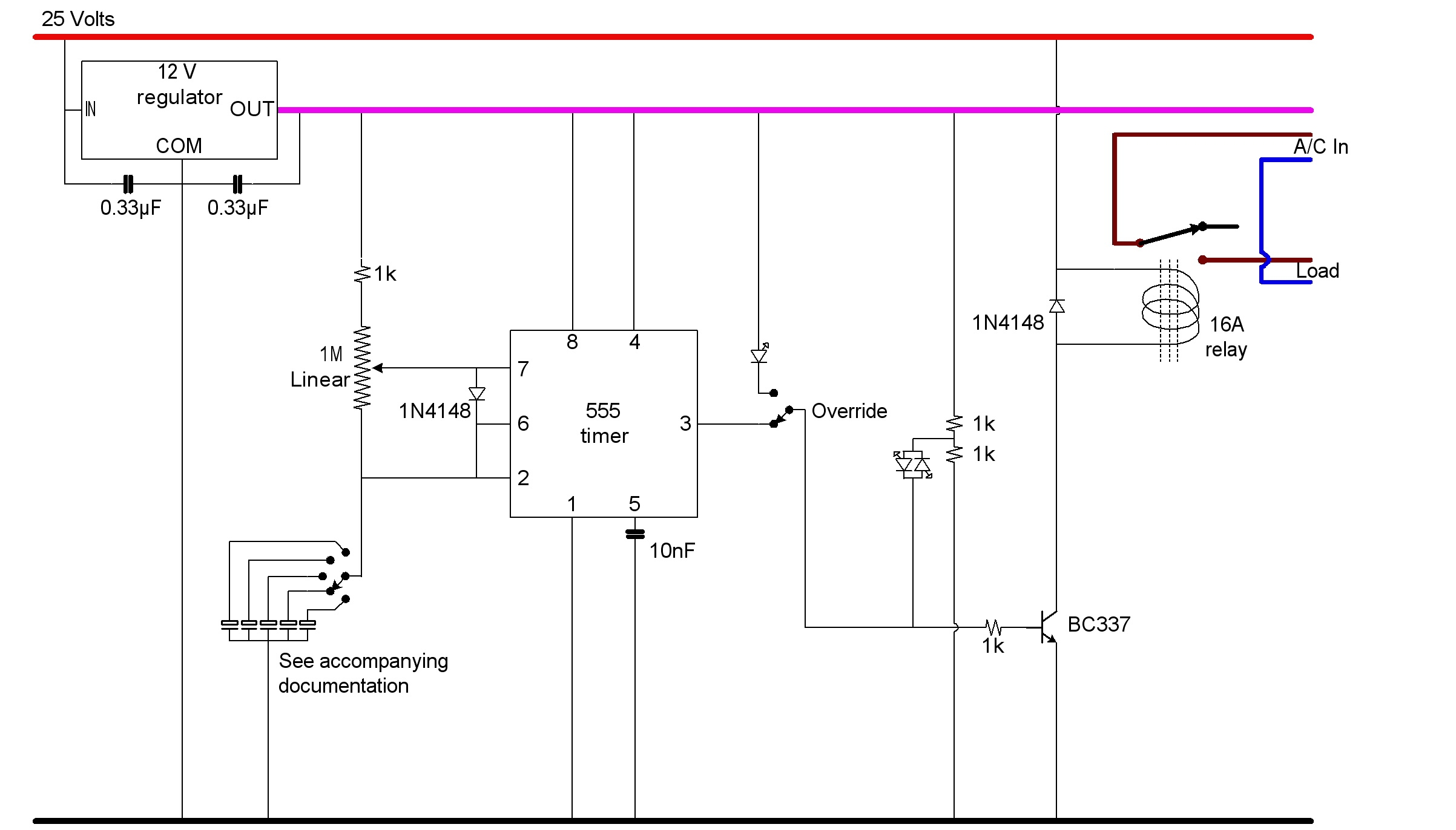
The circuit speaks largely for itself; I only need to expand on the following:
- The switched electrolytic capacitors connecting pins 2/6 to earth via the switch.
- These provide for item 2 in the specification list - the selectable period. The switch I bought from BitsBox is a 12 position switch but it comes with a washer which has a tab on it. Fitting this washer over the spindle with the tab poking into the switch allows you to choose how many positions the switch can reach. I'd advise against buying all the capacitors that I did; for the kettle element in my Electrim bin the 5 second period is good, so you might want to dispense with the switch altogether.
If not then this spreadsheet shows calculations for the duty cycle, for the capacitors you will require for the period switch and for lots of periods (right over on the right).
- The diode between pins 6 and 7.
- This provides for item 1 in the specification list. This diode allows the duty cycle to be varied between 0% and 100%. For an explanation click here . This link also shows the formulae used in the spreadsheet.
- The override switch
- This provides for item 3 in the specification list. In normal operation the output signal from the 555 timer drives the BC337 into saturation and then off again thus energising and releasing the relay coil; this is ideal for simmering. However when you want to bring the bin contents up to the boil you want the relay energised continuously. When the pot is set to 100% I can't hear any clicking from the relay so it appears that the switch is redundant. However during the design I couldn't be sure that I wouldn't be wasting some of the 107 cycles so I incorporated the override switch. This drives the BC337 into saturation via the single colour LED which thus acts as an "Override" indicator providing for item 5 in the specification list.
- The Bicolour LED
- This provides for item 4 in the specification list. In normal operation, as well as driving the transistor, the 555 timer output also sources and sinks current through the bicolour LED which thus acts as a "Power" indicator allowing you a visual sense of the duty cycle by the red to green periods.
- The diode connected across the relay coil.
- This dissipates the energy stored in the coil as a result of the collector current flowing through it when that current stops. This means that the back EMF from the coil is correspondingly reduced which in turn reduces the risk of damaging the transistor.