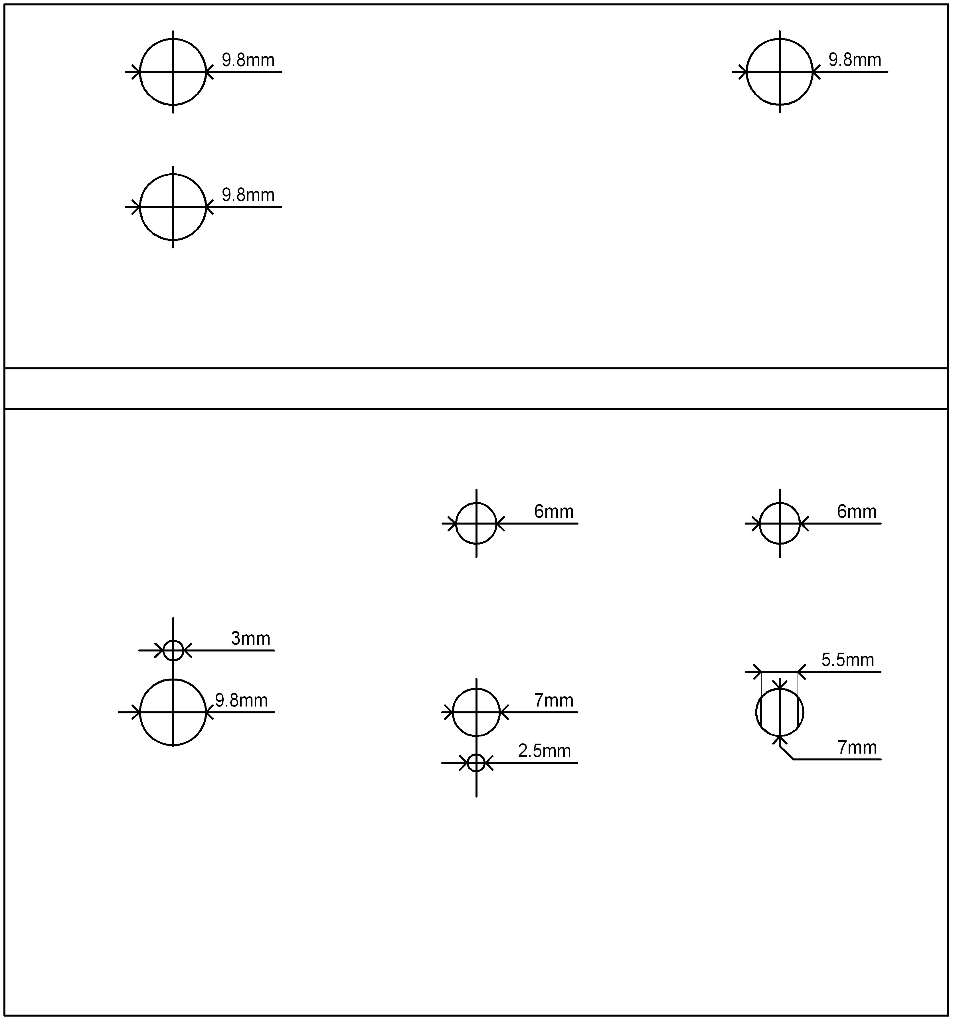
These .jpg images should be just right for you to print out and glue to the box. First, obviously, stick on the hole template and drill the holes. This image is intended to be folded over the edge so that the cable entry holes are on the back of the box. Note. The hole for the "Override" switch should be drilled with a 5.5mm drill and then filed up and down to 7mm because the switch has flats on each side to stop it wobbling.
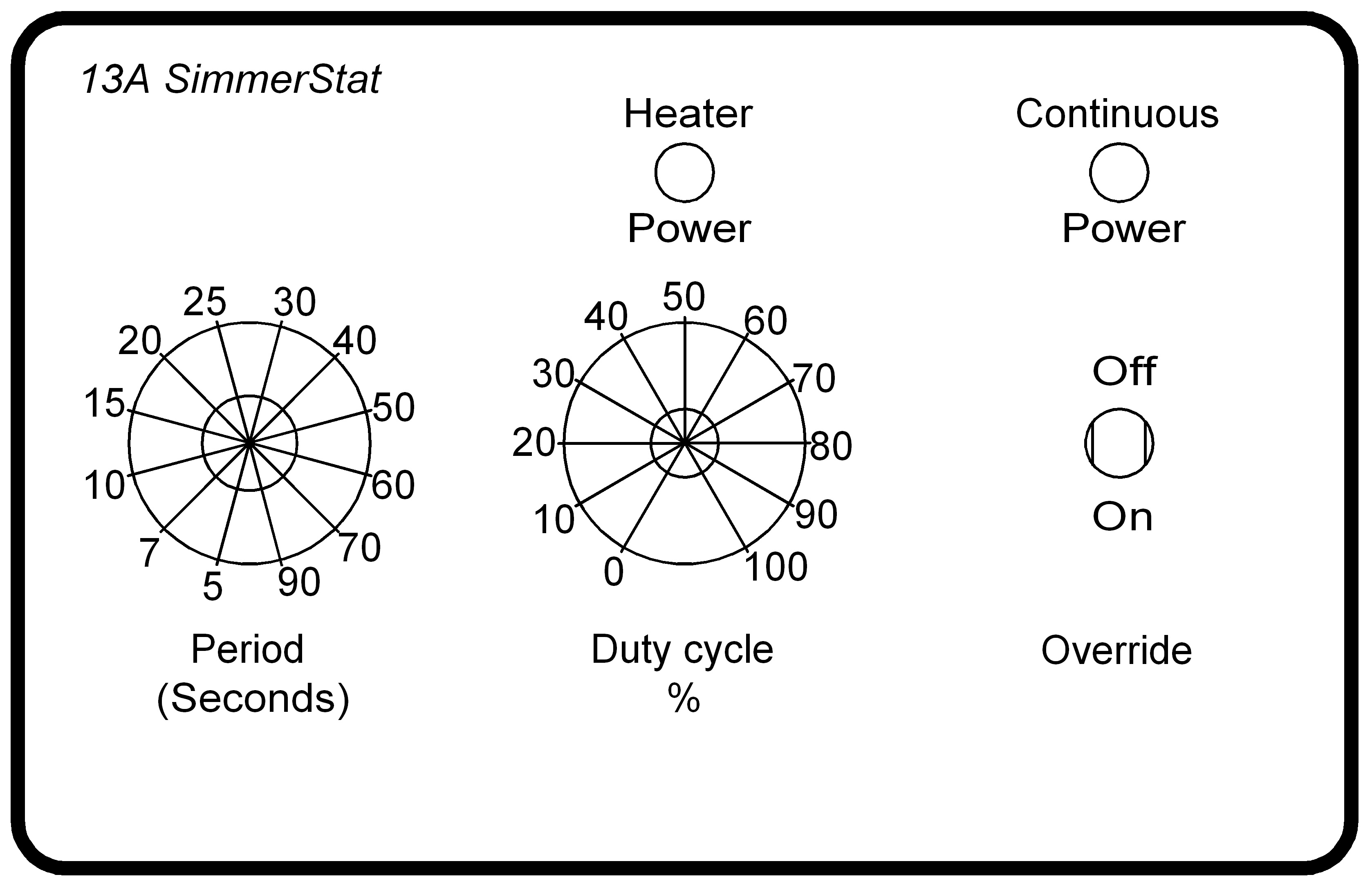
Then print the front panel and laminate it if you have the equipment; cut out the holes for the spindles and glue it to the top of the box with it's holes aligned with the holes you drilled in the box.
Note. If you choose to provide fewer "Period" options you will need to drill the small 3mm hole which is above the 9.8mm hole on the top in a different place so that the switch's travel is symetrical about a vertical line. You'll also have to change the front panel artwork of course.
I created these using a CAD application and then printed them from it, so all was well with the scale of my images. But since you might not have the CAD program I exported them as the .jpg files. I checked in Paint Shop Pro 7 and found that the image information was correct with respect to the sizes.
However you'll need to check them for yourself with whatever image software you use.